

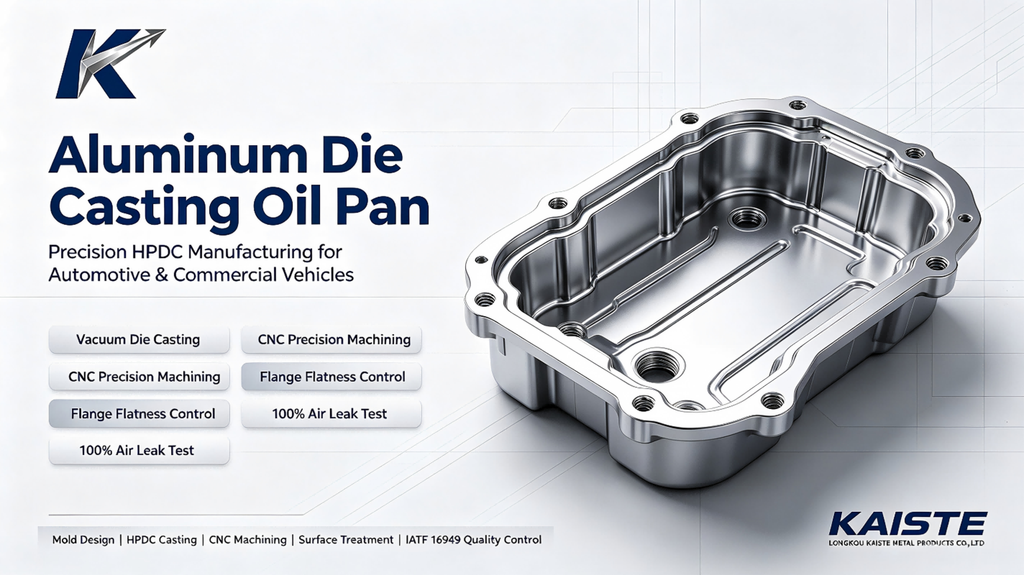
Key Considerations for Casting and Machining of Aluminum Alloy Oil Pans
I. Notes on Die Casting Process (Vacuum High Pressure Die Casting, HPDC)
1. Material Selection & Molten Aluminum Control
- Common grades: ADC12 / A380. Strictly control gas content, impurities and Fe content (excessive iron will easily cause pinholes and brittle phases).
- Molten aluminum temperature: 640~670℃. Refining, degassing and slag removal are required to reduce hydrogen content and minimize porosity from the source. Spectral composition test shall be performed for each furnace sample.
- The oil pan is a pressure-bearing sealing component. Oxide slag inclusion in molten aluminum is forbidden. Concentrated slag holes are not allowed near the sealing flange surface.
2. Mold Design & CAE Pre-simulation (Moldflow / Magma)
- Oil pans feature deep inner cavities and large flange areas. Filling and solidification simulation for gating & venting system must be carried out to predict hot spots, gas entrapment and cold shut locations.
- Adopt vacuum die casting with sealed mold and vacuum valve, vacuum level controlled within 50 mbar, to greatly reduce internal porosity (porosity is the primary cause of oil leakage).
- Add high-pressure point cooling at hot spot areas (oil passages, filter brackets, thick bosses) to prevent shrinkage cavities and porosity; avoid thick hot spots on the flange sealing surface.
- Venting slot depth: 0.05~0.1 mm, arranged at the end of material flow for fast gas exhaust. Reasonable draft angle to prevent sticking and mold drag.
- Machining allowance planning: reserve proper machining allowance for the flange sealing surface. The allowance cannot be too thin (to avoid exposing subcutaneous pores after machining), nor excessively large (which will lead to heavy cutting and stress deformation).
3. Die Casting Process Parameters
- Preheat mold to 150~250℃ to stabilize mold temperature and reduce thermal stress and cracking risk of castings.
- Match injection speed and boost pressure: stable low-speed phase and smooth high-speed filling phase to avoid turbulent flow and gas entrapment.
- Spraying control: uniform coating. Insufficient local coating leads to mold sticking; excessive coating may enter the cavity and form pores.
4. Preliminary Inspection of Raw Castings
- Visual inspection: no cracks, cold shuts, severe mold sticking or short shot; no chipping or damage on flange edges.
- X-ray flaw detection: porosity control on sealing surface and oil passage areas. Pore diameter ≤0.3 mm generally for sealing zones; internal porosity in accordance with ASTM E505 standard.
- Remove sprues and burrs. Do not strike the flange sealing surface to prevent local damage and microcracks.
- Stress relief by natural aging / low-temperature treatment for raw castings to release residual die-casting stress and prevent slow deformation after CNC machining.
II. Core Notes for CNC Machining (Critical, Flange Sealing Surface)
The biggest failure risk of oil pans: poor flange flatness → sealing leakage
1. Fixturing & Clamping (Top priority for deformation prevention)
- Hard single-point clamping is prohibited. Use multi-point conformal fixture with auxiliary supports. Distribute clamping force on rigid reinforcing ribs; do not directly clamp thin-wall flange surface, to avoid collapse and clamping deformation.
- Separate rough machining and finish machining. Loosen clamps after roughing to release cutting stress, re-align and then finish-machine the flange sealing face.
- Complete multi-side machining in one clamping setup whenever possible to reduce repeated positioning error.
2. Machining of Sealing Flange Surface
- Flatness requirement: typically 0.03~0.08 mm for passenger car oil pans (per customer drawing), surface roughness Ra 1.6~3.2 μm to ensure good fit with gaskets/sealant.
- Tool selection: diamond or carbide end mills dedicated for aluminum alloy. High spindle speed with small cutting depth to reduce cutting heat; high temperature will cause thermal deformation of aluminum parts.
- Small cutting allowance for finishing; tool marks, scratches and edge chipping on flange after machining are forbidden. Tiny scratches may result in oil seepage.
3. Machining of Threaded Holes, Oil Drain Holes and Oil Passages
- Threaded holes: control tapping torque to avoid thread stripping and burrs; deburr hole edges. Falling burrs may enter the engine and cause wear.
- Oil passages and drain plug holes: tight dimensional tolerance with hole edge chamfering; no internal cutting burrs.
Automobile engine requirement: VDA19 technical cleanliness. Inner cavities must be thoroughly flushed and blown free of aluminum chips after machining. Residual chips will bring severe risks of engine damage.
4. Dimensional Control after Machining
Full dimensional inspection for first articles; monitor flange flatness and hole position via SPC during mass production. Re-measure after 24-hour standing post-machining to check deformation induced by stress release.
III. Post-treatment & Air Tightness Test (Mandatory before delivery)
- Deburring & cleaning: high-pressure spraying + compressed air purging. No aluminum chips or cutting dust inside cavities. Perform VDA19 cleanliness test for key customers.
- 100% on-line air tightness test (extremely important)
- Inner cavity pressure holding test: commonly 0.2
0.4 MPa pressure hold for 2030s to detect leakage rate; separate high-pressure leak test for oil passages. - Leakage rejected parts shall not be concealed by unauthorized repair. Impregnation repair can be evaluated only with customer approval; high-end OEMs usually do not allow impregnation.
- Inner cavity pressure holding test: commonly 0.2
- Surface protection: passivation / cleaning for rust prevention. Store with protective covers on flange sealing surfaces to avoid bumping and scratching.
IV. Common Failure Risk List (Available for DFM review with customers)
✅ Porosity / shrinkage → exposed after machining → oil seepage (solved primarily by vacuum die casting)
✅ Flange deformation from machining stress → out-of-spec flatness → assembly leakage
✅ Residual aluminum chips and burrs inside cavity → engine cylinder scoring and bearing wear
✅ Excessive clamping force causing indentation and deformation of thin-wall flange
✅ Concentrated shrinkage defects at hot spots near sealing surface
✅ Bumping and scratching of sealing flange surface during handling